

← Back to FAQ
Front-Load NAS Backplane
Looking to upgrade your NAS case, or wondering what's changing with the new models? Here's how the backplane connects, what comes in the retrofit kit, and what to expect when installing it.
If you already have a compatible CX3701, CX3702, CX4712, or CX4713, you can upgrade it with the KIT-NAS-RETROFIT kit.
If your case shipped before July 2024, we still need to verify compatibility. Please check with us before ordering a kit for an earlier case.
Choose data cables that match the connections on your motherboard or HBA. We recommend using an HBA; compatibility will depend on the controller and drives you're using.
They let you connect two additional SSDs using short SATA cables between the SSDs and the backplane. Their data travels through the two remaining channels on the third SFF-8643 connection.
Think of them as connections to your SSDs. They aren't inputs for connecting the backplane to motherboard SATA ports.
The included cables give you two ways to connect power:
Each power input also has a capacitor to help manage inrush current and brief load spikes.
We recommend an HBA. If you're unsure about a particular motherboard, controller, and drive combination, check with us before choosing your cables.
SATA power pin P11 is used for drive activity indication on this board.
You'll replace the original drive connector assembly with the new bracket and backplane. With the PCB mounted to the bracket before installation, you only need to slide the drives forward far enough to unplug them from the old connectors. They don't need to come all the way out.
You can leave the motherboard tray fully or partly installed, although taking it out gives you more room to work.
The fan brace, or fan wall, can stay in place if your PH2 screwdriver is long enough to reach the screws. If you'd like more working room, remove the brace's four PH2 flat-head screws through the bottom of the case and take the brace out too.
2. Make room for your screwdriver. If you need more screwdriver clearance, remove the four tray-retaining screws at the rear of the case (two on each side), and slide the motherboard tray back far enough to reach the connector assembly. You can leave the tray fully installed if you have enough room, or remove it completely if that's easier. Disconnect the old drive power and data cables before or after moving the tray, as access allows, without pulling on connected cables.
3. Clear access and disengage the drives. For the CX4712/CX4713, remove the 5.25-inch devices and bay brackets, plus the tool-less fan mounting bracket. Remove the fan brace too if you need more room, as described above. On all four models, slide the drives forward far enough to unplug them from the old connectors.
4. Remove the motherboard-side metal. Take out the four black hex-head screws facing the motherboard and the two silver flat-head screws on top of the connector assembly. Remove that piece of metal, followed by the ten individual SATA/SAS-to-SATA passthrough connectors.
5. Remove the drive-side metal. Take out the four black hex-head screws along its top edge, facing the motherboard and fastening into the upper drive guide. Then remove the four silver flat-head screws fastening downward into the lower drive guide. Lift out the remaining piece of metal.
6. Fit the retrofit assembly. The PCB is planned to arrive mounted to the bracket. If it isn't already attached, mount it using eight black hex-head screws before fitting the assembly into the case. Secure the bracket to the drive cage with the supplied replacement screws: four black hex-head screws and four silver flat-head screws in the mounting positions from step 5.
7. Align the backplane. We recommend checking the alignment to account for small differences between cases. Loosen the eight screws securing the PCB to the retrofit bracket just enough to let the board move. Slide drives into bays 2 and 8 (this leaves all eight screw heads accessible), counting bay 1 as the bay nearest the power button, and let the drive connectors guide the board into position. With those two drives seated, tighten the eight PCB screws.
8. Put everything back and connect the cables. Slide the remaining drives back into the new connectors. Reinstall any fan brace you removed using its four bottom-mounted screws, followed by the fan mounting bracket and fans. Reinstall any 5.25-inch bay brackets and devices. If you moved the motherboard tray, return it to position and secure its four retaining screws—two on each side. Connect the backplane's power and data cables, keeping the cables clear of the tray as you move it.
9. Start up and check your drives. Return the server to the rack, reconnect the system, and check that your controller and operating system detect the connected drives.
Will the backplane come with new cases, or is it an upgrade?
Both! Our upcoming NAS cases will include the PCB backplane and power cables as standard. We'll install the backplane before the case ships, so you'll just need to hook up power and data cables.If you already have a compatible CX3701, CX3702, CX4712, or CX4713, you can upgrade it with the KIT-NAS-RETROFIT kit.
Will the retrofit fit my case?
The kit fits CX3701, CX3702, CX4712, and CX4713 cases shipped since July 2024. All four models use the same mounting bracket, backplane, and power cable set, so there's just one retrofit kit to choose from.If your case shipped before July 2024, we still need to verify compatibility. Please check with us before ordering a kit for an earlier case.
What's included in the retrofit kit?
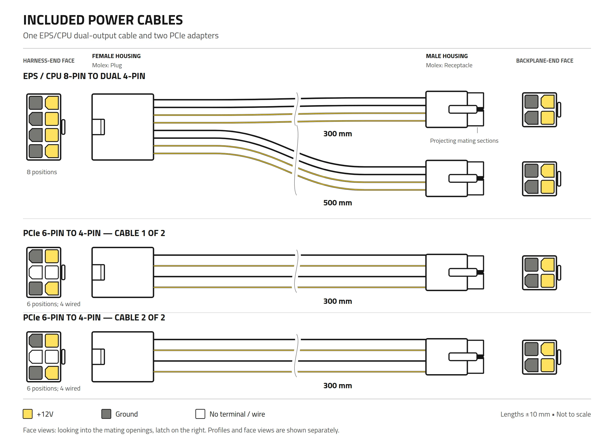
You'll get the retrofit mounting bracket, PCB backplane, replacement mounting screws, and three power cables:- Two 10" PCIe six-pin-to-backplane cables.
- One EPS/CPU-to-dual-backplane Y cable. One leg of the cable is 10" and the other leg is 18".
How do the data connections work?
The ten drive bays connect through three SFF-8643 (Mini-SAS HD) ports. Each cable carries data for up to four drives:- First SFF-8643 port: Drives 1–4
- Second SFF-8643 port: Drives 5–8
- Third SFF-8643 port: Drives 9–10, with two channels left over
Choose data cables that match the connections on your motherboard or HBA. We recommend using an HBA; compatibility will depend on the controller and drives you're using.
Where can I find the connector part numbers and specs?
If you'd like to check the connector details against your drives or cables, here are the parts we're using:- Drive-side SAS connector: Amphenol 10120818-001C-TRLF — SAS connector family datasheet (PDF)
- Controller-facing SFF-8643 (Mini-SAS HD) connector: Amphenol G40H11331HR — G40H connector family datasheet (PDF)
What are the two extra SATA ports for? Does the retrofit have them?
The retrofit board doesn't have those ports. We're planning to include them on the boards for the new cases.They let you connect two additional SSDs using short SATA cables between the SSDs and the backplane. Their data travels through the two remaining channels on the third SFF-8643 connection.
Think of them as connections to your SSDs. They aren't inputs for connecting the backplane to motherboard SATA ports.
How do I power the backplane?
There are two four-pin power connectors on the board, arranged in a 2×2 Molex plug. One powers drive bays 1–5, and the other powers bays 6–10.The included cables give you two ways to connect power:
- Use two PCIe six-pin connections from your PSU's cable harness, with one adapter going to each backplane power input.
- Use one EPS/CPU connection from your PSU's cable harness, with the included Y cable feeding both backplane power inputs.
Can I have custom cables made for a modular PSU?
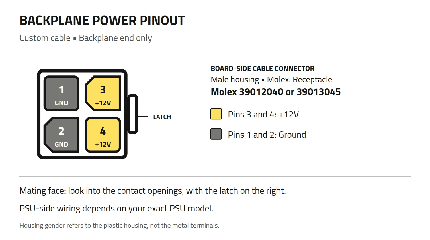
Yes. For the backplane end of a custom cable, use a four-pin Molex 39012040 or 39013045 connector. The board-side pinout is:- 1 and 2: Ground
- 3 and 4 (the pair nearest the latch): +12V
Does the board generate its own 5V power?
Yes. Each power input carries two 12V connections and two grounds, and the board converts 12V to 5V where the drives need it. It doesn't supply 3.3V.Each power input also has a capacitor to help manage inrush current and brief load spikes.
Do I need special software or a particular operating system?
The backplane itself has no operating system requirements. Your motherboard or HBA still needs to support the drives you're connecting, along with any drivers that controller normally requires.We recommend an HBA. If you're unsure about a particular motherboard, controller, and drive combination, check with us before choosing your cables.
Does it support staggered spin-up?
The backplane doesn't sequence drive power on its own. Staggered spin-up depends on support from your HBA/controller and drives.SATA power pin P11 is used for drive activity indication on this board.
How difficult is the retrofit to install?
Plan on about 20–30 minutes and a PH2 Phillips screwdriver. There's no drilling or case modification involved.You'll replace the original drive connector assembly with the new bracket and backplane. With the PCB mounted to the bracket before installation, you only need to slide the drives forward far enough to unplug them from the old connectors. They don't need to come all the way out.
You can leave the motherboard tray fully or partly installed, although taking it out gives you more room to work.
Is there anything different about installing it in a CX4712 or CX4713?
Yes—there are a few more parts to move out of the way. Remove the 5.25-inch devices and their bay brackets, plus the mid-chassis fan mounting bracket, to reach the connector assembly screws. The fans and fan mounting bracket are tool-less.The fan brace, or fan wall, can stay in place if your PH2 screwdriver is long enough to reach the screws. If you'd like more working room, remove the brace's four PH2 flat-head screws through the bottom of the case and take the brace out too.
What are the installation steps?
1. Power down and make room to work. Shut down the system, disconnect power, and take the server out of the rack.2. Make room for your screwdriver. If you need more screwdriver clearance, remove the four tray-retaining screws at the rear of the case (two on each side), and slide the motherboard tray back far enough to reach the connector assembly. You can leave the tray fully installed if you have enough room, or remove it completely if that's easier. Disconnect the old drive power and data cables before or after moving the tray, as access allows, without pulling on connected cables.
3. Clear access and disengage the drives. For the CX4712/CX4713, remove the 5.25-inch devices and bay brackets, plus the tool-less fan mounting bracket. Remove the fan brace too if you need more room, as described above. On all four models, slide the drives forward far enough to unplug them from the old connectors.
4. Remove the motherboard-side metal. Take out the four black hex-head screws facing the motherboard and the two silver flat-head screws on top of the connector assembly. Remove that piece of metal, followed by the ten individual SATA/SAS-to-SATA passthrough connectors.
5. Remove the drive-side metal. Take out the four black hex-head screws along its top edge, facing the motherboard and fastening into the upper drive guide. Then remove the four silver flat-head screws fastening downward into the lower drive guide. Lift out the remaining piece of metal.
6. Fit the retrofit assembly. The PCB is planned to arrive mounted to the bracket. If it isn't already attached, mount it using eight black hex-head screws before fitting the assembly into the case. Secure the bracket to the drive cage with the supplied replacement screws: four black hex-head screws and four silver flat-head screws in the mounting positions from step 5.
7. Align the backplane. We recommend checking the alignment to account for small differences between cases. Loosen the eight screws securing the PCB to the retrofit bracket just enough to let the board move. Slide drives into bays 2 and 8 (this leaves all eight screw heads accessible), counting bay 1 as the bay nearest the power button, and let the drive connectors guide the board into position. With those two drives seated, tighten the eight PCB screws.
8. Put everything back and connect the cables. Slide the remaining drives back into the new connectors. Reinstall any fan brace you removed using its four bottom-mounted screws, followed by the fan mounting bracket and fans. Reinstall any 5.25-inch bay brackets and devices. If you moved the motherboard tray, return it to position and secure its four retaining screws—two on each side. Connect the backplane's power and data cables, keeping the cables clear of the tray as you move it.
9. Start up and check your drives. Return the server to the rack, reconnect the system, and check that your controller and operating system detect the connected drives.
Which new cases are replacing the current models?
The current models will reach end of life at the end of 2026. Here is what will be replacing them:- CX3701: CX3150n
- CX3702: CX3180n
- CX4712: CX4250n
- CX4713: CX4280n